

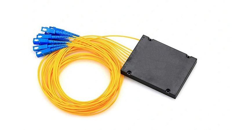


A neighborhood access network can look economical when its design spreads the feeder cost across many premises. The calculation becomes less convincing if the farthest connections lack optical margin, spare outputs remain unused or a routine repair requires repeated visits to difficult locations. Split capacity is only part of the decision.
A PLC splitter, a fiber optic patch cord and an optical transceiver each have a place in the network, but they do different jobs. For businesses funding connectivity, split ratio and maintenance cost must be considered together. A design should explain who can be connected, under which optical limits, and how technicians will restore service when something fails.
What a PLC splitter does in an access network
FOA describes the passive optical network splitter as distributing downstream signals and combining upstream paths toward a shared network port. The passive distribution plant reduces the need for powered equipment between the operator and the subscriber. It does not eliminate the equipment at either end.
Begin with the service area. Identify the premises to be reached, their routes and likely connection sequence before choosing a split ratio, because an evenly drawn set of outputs on a planning diagram can conceal very different installation distances and access conditions on the ground. Survey those differences early.
Where it stops: a passive component cannot correct every planning error. The design still has to satisfy equipment limits and practical installation requirements. A low component price should not be used to close those questions before the responsible network designer has checked the complete paths.
Split ratio is a service decision before a stock decision
T&S Communications lists a 1 x 2 mini PLC splitter without connectors and a 1 x 8 bare version without connectors. These entries describe input and output configurations as well as packaging. They are starting points for a design choice, not interchangeable quantities of the same installation.
Compare the planned connections with realistic service demand. Separate premises passed from customers ready to connect, and identify where spare capacity would sit if demand arrives in another part of the area. Unused outputs cannot be treated as revenue or as automatically accessible capacity elsewhere.
Where it stops: the largest available split ratio may distribute capacity to places that do not need it while leaving awkward routes for those that do. Show the intended connection sequence on the design, then assess whether later growth can be accommodated without disturbing established services.
The optical transceiver cannot replace a path budget
Optical power must remain within the selected equipment’s operating requirements. Have the designer calculate the complete path, including the splitter, fiber, splices and connectors, then check the relevant operating wavelengths and allowances rather than accepting a calculation that includes only the most visible component. Keep the calculation tied to identified parts.
Record the optical transceiver and subscriber equipment specifications used in that calculation. Explain both the longer, weaker path and any short path that needs a separate check. Request the applicable limits instead of borrowing a budget from a different network generation or a neighboring project.
Where it stops: changing active equipment is not a substitute for understanding an unsuitable distribution path. If a proposed split ratio leaves insufficient margin, revisit the route and topology before assuming that a more expensive optical transceiver will provide an acceptable remedy. The whole design needs checking.
Packaging determines who can repair the fiber optic splitter
The same T&S Communications range includes a 1 x 4 version with SC/APC connectors and a breakout box, a connectorless bare-fiber listing using 250 μm fiber, and a mini listing using 900 μm loose tube. Packaging and termination details therefore belong beside the split ratio in the specification.
Ask the maintenance team how the selected fiber optic splitter will be installed and replaced. Check the enclosure, routing space, splice management and access requirements against its actual dimensions and termination style, so that the installation method is decided while the design can still be changed economically. Include the required tools and skills.
Where it stops: a bare component is not a complete outdoor installation. Its surrounding enclosure and fiber management must suit the location. Compare quotations at the installed-assembly boundary rather than comparing a bare splitter price with a packaged solution and calling the difference a saving.
A fiber optic patch cord changes the maintenance boundary
Connectorized arrangements can make replacement and testing more accessible, but the project must provide suitable access, identified patching and a cleaning procedure. A fiber optic patch cord placed in an overcrowded cabinet may be easy to specify on paper and difficult to handle without disturbing adjacent services.
Walk through a proposed repair. Identify which connection the technician would isolate, where the test instrument would connect and how the correct spare would be recognized, including what happens if the cabinet label has faded or the original installer is no longer available to explain the route. Labels need a matching record.
Where it stops: maintenance cost cannot be predicted from connector count alone. Compare actual work requirements, site access and replacement boundaries. Retain the approved patching details with the splitter records so that a routine spare order does not introduce an incompatible polish or an unsuitable assembly.
Wavelength division multiplexing is a separate design question
FOA explains that passive optical networks use different wavelengths for traffic directions, and that compatible generations can share a distribution network through wavelength arrangements. Wavelength division multiplexing and power splitting therefore solve different problems. A splitter’s port count alone does not establish upgrade compatibility.
Document the present service and the intended upgrade separately. Ask which components remain, what coexistence equipment would be needed, and which optical limits apply after the change. Keep future capacity claims conditional until those details have been checked against the actual installed components.
Where it stops: calling a passive plant “future ready” provides no testable acceptance condition. When reviewing components from T&S Communications, obtain the applicable product documentation and ask the network designer to confirm it against the proposed service. A supplier’s product range is not a guarantee for an unspecified future network.
Locate the failure boundary before estimating operating costs
Put the repair boundary on the drawing. Identify which users depend on each shared path and which enclosure must be opened to investigate a fault, because the cost of diagnosis can depend as much on access permissions and route identification as on the price of the failed component itself. Include those practical constraints in the review.
Compare installation alternatives using explicit assumptions: technician availability, site travel, spare storage, access hours and service restoration work. Avoid inventing a universal saving percentage. A documented local estimate is more useful than a promotional claim that applies to an undefined network and excludes the work your own team must perform.
Where it stops: fewer powered field devices do not mean maintenance disappears. Fiber routes, enclosures and connections still need inspection and repair. Assign ownership for the records and spares before commissioning; an incomplete handover can turn a modest component failure into a prolonged search for the correct path.
Approve the service plan with the splitter order
A useful approval package contains the service-area drawing, connection forecast, optical calculation, component list and maintenance method. Link each unresolved assumption to someone responsible for closing it. Distinguish the capacity installed today from the capacity that becomes usable only after additional equipment or field work.
For an enterprise or community project, explain the expected service boundary in plain language. State what the installation will support, how connections will be added and where the repair responsibility lies. Those answers make the spending decision easier to evaluate than a table of splitter prices alone.
The cost boundary: an inexpensive PLC splitter is useful only within a network that can deliver and maintain the intended service. Select the split ratio alongside the optical design and repair plan. Preserve that reasoning with the handover documents so later expansion starts from an understood network.